How does robot_localization use the IMU data to update the EKF/UKF in their sensor fusion algorithm ? Robot pose can be obtained from IMU data using multiple techniques, and I am curious which one robot_localization package uses.
↧
Pose from IMU measurements
↧
Navsat_transform in robot_localization gives sightly rotated gps odometry
Hi, I have been having this problem for a week or so.
I am trying to fuse the GPS position with an IMU simulated in Gazebo(hector_sensors) with the robot_localization package (with one EKF node and one navsat node ).
So far it everything was OK, I rotated everything as the REP103 states and the data seems to give good covariances.
However, the GPS(or the navsat node rather) has a steady drift of approximately 1~2º in the /odometry/gps & /odometry/filtered topics and after traveling a long distance , it becomes a problem.
The movement is along the Y axis, but after 100 meters or so, it drifts a meter on the y axis.
It seems to be an extra rotation and I cannot retrieve the proper coordinates( i.e. getting the global reference of the robot).
At first I though it should be rotated with the utm->odom transform published by navsat_transform_node but I can't figure it out how.
Do you know what my problem is?, i am almost certain that it has to be something regarding the map-utm transformation but can't get it to work.
**Launchfiles:**
[Navsat:](https://pastebin.com/tGQe4kPZ) , [EKF](https://pastebin.com/GwHhu3RQ)
**Yaml config parameters** [Navsat](https://pastebin.com/DPxR5hz8) , [EKF](https://pastebin.com/GtK3hZsf)
**Sensor model gazebo** [model.sdf](https://pastebin.com/tQPqT8Us)
[And a photo of the odometry results](http://imgur.com/a/YXd6b)
Thanks a lot, it you need anything else let me know.
↧
↧
robot_localization and angular velocity for better odometry
Dear all,
If I input angular velocity and odometry pose data into robot_localization, can we improve odometry pose estimation due to angular velocity fusion from IMU?
Based on my understanding of robot_localization's code, it will not improve odometry pose estimation. Am I right? The reason of my assumption is that I cannot find correction of pose estimation based on angular velocity fusion in robot_localization's code.
If we want to improve odometry pose estimation, we must input orientation information IMU. Am I right?
Assuming that we can improve odometry pose estimation based on orientation information, does anyone know the minimum accuracy of orientation of IMU to see the meaningful improvement? For example, if my IMU orientation has accuracy of 10 or 20 degrees, is it acceptable to achieve better odometry pose estimation?
Thanks in advance for your reading and answer.
↧
Can navsat_transform be used to transform a pose from latlong to odom?
I'm using a gps to localize a mobile robot and `ekf_localization_node` together with a `navsat_transform_node` to transform the robot location into a local `odom` frame.
I would like to be able to send the robot gps-coordinates and use the functions from `robot_localization` to transform them into the `odom` frame. However, `navsat_transform` only publishes `odom->utm` and I don't think there are any `latlong->utm` conversion exposed to the user.
What I'm trying right now is to use the [utm package](https://pypi.python.org/pypi/utm) in python to convert latlong coodrinates into utm and then using the `utm->odom` transform provided by `navsat_transform_node` to get the local coordinates:
utm_coords = utm.from_latlon(latlong[0], latlong[1])
# create PoseStamped message to set up for do_transform_pose
utm_pose = PoseStamped()
utm_pose.header.frame_id = 'utm'
utm_pose.position.x = utm_coords[0]
utm_pose.position.y = utm_coords[1]
# get the utm->odom transform using tf2_ros
tfbuffer = tf2_ros.Buffer()
tflistener = tf2_ros.TransformListener(tfbuffer)
T = tfbuffer.lookup_transform('odom', 'utm', rospy.Time())
# apply the transform
odom_pose = tf2_geometry_msgs.do_transform_pose(utm_pose, T)
It seems to work, but I would prefer to use the conversions implemented in robot_localization if possible, for consistency.
↧
robot_localization and bag file output
Dear all,
Have anyone tried to run the test1.bag , test2.bag and test3.bag files included in the robot_localization package? Do you have any screen shot for correct output from these bag files and corresponding launch files? I would like to try them and compare the results with mine.
If you have them, could you please share with me?
If you have any other working samples especially (IMU + Raw Odometry), could you please share with me?
Best Regards
Min Latt
↧
↧
robot_localization test bagfiles
Hi!
Does any one know what is the expected output of 3 bagfiles included in robot_localization package?
[test1.bag](https://github.com/cra-ros-pkg/robot_localization/blob/indigo-devel/test/test1.bag)
[test2.bag](https://github.com/cra-ros-pkg/robot_localization/blob/indigo-devel/test/test2.bag)
[test3.bag](https://github.com/cra-ros-pkg/robot_localization/blob/indigo-devel/test/test3.bag)
Like screencapture or plot of robot path?
This may help me check if I am running the robot_localization correctly.
Thanks!
↧
robot_localization output sample
Hi All,
I have found out the following paper from robot_localization package folder.
robot_localization_ias13_revised.pdf
Does anyone have the bag file for the following output from Page 4 of robot_localization_ias13_revised.pdf?

Thanks in advance for your support.
Best Regards
Min Latt
↧
Is there an existing speed control node to connect the robot_localization state estimator with the diff_drive_controller?
I am using ROS Indigo on a differential drive robot for indoor use (no GPS). The path is pre-determined and the velocity along the path is to be controlled. I believe that move_base node would be overkill and probably would not work in this case. Speed along path needs to be at a certain rate and if an obstacle is detected the unit will stop and send an alarm. I think a 2-D PID speed controller (linear and angular vel.) and a path planner that reads from the pre-planned path and provides the commanded 2-D speed is all that is needed. Is there an existing ROS node I could use or modify?
↧
robot_localization and gmapping - gps has offset
Trying to use robot_localization with gps to improve the accuracy. Currently, gmapping is responsible for map->odom transform. So, I have tried the following configuration. We use base_footprint instead of base_link. Otherwise we have tried to follow REP-105.
launch file (for robot_localization):
↧
↧
robot localization initial position
Hi,
I am using robot localization to fuse odomtery, imu, and rtk gps data. Since the gps data is rtk its published a relative distace to a nearby base station, meaning I don't need to use the navsat transform node. My gps base station is the origin of my map frame and my robot usually initializes around x = -180 y = -80.
I'm finding that when I initialize, the initial position is set to (0,0) and it takes the kalman filter around 40 seconds to drift over to (-180,-80) where the robot actually is. I logged my gps data in a bag file to make sure that it wasn't publishing (0,0) initially, which its not.
How do I tell robot_localization what my actual initial position is? I had the thought that I could increase the covariance on my initial position, here is what it is currently:
[1e-9, 0, 0, 0, 0, 0, 0, 0, 0, 0, 0, 0, 0, 0, 0,
0, 1e-9, 0, 0, 0, 0, 0, 0, 0, 0, 0, 0, 0, 0, 0,
0, 0, 1e-9, 0, 0, 0, 0, 0, 0, 0, 0, 0, 0, 0, 0,
0, 0, 0, 1e-9, 0, 0, 0, 0, 0, 0, 0, 0, 0, 0, 0,
0, 0, 0, 0, 1e-9, 0, 0, 0, 0, 0, 0, 0, 0, 0, 0,
0, 0, 0, 0, 0, 1e-9, 0, 0, 0, 0, 0, 0, 0, 0, 0,
0, 0, 0, 0, 0, 0, 1e-9 ,0, 0, 0, 0, 0, 0, 0, 0,
0, 0, 0, 0, 0, 0, 0, 1e-9 ,0, 0, 0, 0, 0, 0, 0,
0, 0, 0, 0, 0, 0, 0, 0, 1e-9, 0, 0, 0, 0, 0, 0,
0, 0, 0, 0, 0, 0, 0, 0, 0, 1e-9, 0, 0, 0, 0, 0,
0, 0, 0, 0, 0, 0, 0, 0, 0, 0, 1e-9, 0, 0, 0, 0,
0, 0, 0, 0, 0, 0, 0, 0, 0, 0, 0, 1e-9 ,0, 0, 0,
0, 0, 0, 0, 0, 0, 0, 0, 0, 0, 0, 0, 1e-9, 0, 0,
0, 0, 0, 0, 0, 0, 0, 0, 0, 0, 0, 0, 0, 1e-9, 0,
0, 0, 0, 0, 0, 0, 0, 0, 0, 0, 0, 0, 0, 0, 1e-9]
But that would be a waste of valuable knowledge. I start the robot in the same place each time. I'd like to have a very small covariances to represent that and then set the initial position somehow.
↧
robot_localization and gmapping - how the transform should be done?
We are trying to use `robot_localization` and `gmapping`. What we have done so far: we use gmapping to publish the transform between `map` -> `odom`. Then we tried to apply gps, imu and odom using ekf from robot_localization. We use navsat_transform and one ekf node to fuse all the data. This node does `odom` -> `base_link` transform. This setting does not work very well.
Here: https://roscon.ros.org/2015/presentations/robot_localization.pdf (page 4) there is a picture: 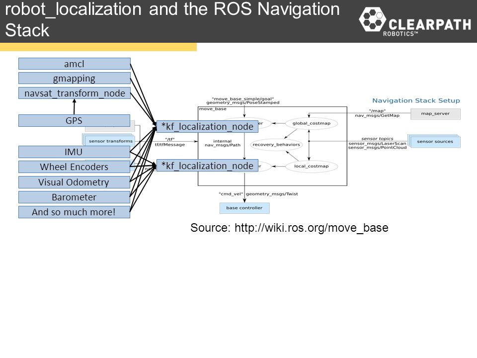
This indicates, that I should fuse gmapping and navsat_transform result in one localization node. Should this be done? How should it be done? Is there an example of it?
↧
IMU convention for robot_localization
Hi all,
I am trying to use one IMU in robot_localization. I am confusing with IMU convention.The symbol in my IMU is as shown in the following figure.

Can I assume that IMU is in ENU format if I make the IMU X direction as the forward direction of the robot?
If my robot is stationary in the flat surface, what should be my linear acceleration value in z direction ? -9.8 or +9.8?
Best Regards
Min Latt
↧
Robot_localization
I'm trying to get the ekf_localization node working on a pioneer 2 using whells odometry and a camera for pose with aruco markers and I'm having problems. When see get a marker and send info to ekf this get angular velocity in z while robot stay in his position.
My launch file is this:
>
↧
↧
robot_localization and IMU selection
Dear all,
I am thinking to buy IMU to be used with robot_localization package. I understand that IMU must be in ENU mode. May I know which IMU support ENU mode and output reliable orientation information? Is microstrain 3DM-GX5-25 a good choice? But it is in NED. Can we use it as ENU via some kind of static transform?
http://www.microstrain.com/inertial/3DM-GX5-25
Best Regards
Min Latt
↧
robot_localization - gps and imu minimal example not working
I have some trouble getting `robot_localization` working. I have tried several configurations but nothing gives me a good result. So I thought I would try to get the minimal working. I have gps data and imu data. I also have wheel odometry. All this is simulated and all the values are currently almost ideal (no or very small noise). I use navsat with the following conf:
navsat_transform:
frequency: 30
delay: 3.0
magnetic_declination_radians: 0 #
yaw_offset: 0
zero_altitude: true
broadcast_utm_transform: true
publish_filtered_gps: true
use_odometry_yaw: true
wait_for_datum: false
And then I use one ekf node with the following conf:
odom0: odom
odom0_config: [false, false, false,
false, false, false,
true, true, true,
false, false, false,
false, false, false]
odom0_queue_size: 10
odom0_nodelay: true
odom0_differential: false
odom0_relative: false
odom1: odometry/gps
odom1_config: [true, true, false,
false, false, false,
true, true, true,
false, false, false,
false, false, false]
odom1_queue_size: 10
odom1_nodelay: true
odom1_differential: false
odom1_relative: false
imu0: imu/data
imu0_config: [false, false, false,
true, true, true,
false, false, false,
true, true, false,
true, true, true]
imu0_nodelay: false
imu0_differential: false
imu0_relative: false
imu0_queue_size: 10
imu0_remove_gravitational_acceleration: true
The conf is pretty taken from the examples.
I have static transform for `map` -> `odom` (they are exactly the same). ekf publishes `odom` -> `base_link` transform. The latitude-longitude are exactly aligned with y and x axis.
Wheel odometry is in odom topic.
**The problem I am facing**: when there is no movement, the filtered odometry (also the transform from `odom` to `base_link`) starts moving slowly (the robot itself is not moving). When the robot is moving, everything gets messy pretty quickly.
I have tried to exclude imu, odom, change covariance, all the other parameters. What is my problem here? I would like to get a minimal example working, which would mainly use GPS.
↧
Help with IMU orientation
Hi,
I am trying to integrate IMU on the pioneer robot. I am using the BNO055 IMU sensor. For visualization I created a child_link from the base_link. The IMU is oriented with axes aligned to front (x axis), left (y axis) and top (z axis) from the [sensors data sheet(pg.24)](https://ae-bst.resource.bosch.com/media/_tech/media/datasheets/BST_BNO055_DS000_14.pdf).
↧
Multiple nodes publishing to same topic in robot_localization package
In robot_localization package, the nodes publish to /odometry/filtered (hardcoded). If there are 2 nodes - one for odom and one for map, which node is writing to this topic ?
↧
↧
robot_localization: How are the sensor measurements being fused?
I was working with the robot_localization package for fusing encoder/IMU/GPS measurements. I wanted to know does the filter fuse the measurements in time? Is it a loosely-coupled fusion? It would be helpful if someone can explain the underlying algorithm for taking in the measurements for correction.
↧
robot_localization IMU TF
Dear all,
If I use robot_localization with [9 Degrees of Freedom - Razor IMU](https://www.sparkfun.com/products/retired/10736), do I need to provide TF between base link and imu link? Is TF between base_link and imu_link important for robot_localization internal processing?
Since this IMU uses three different chips for an accelerometer, gyroscope and magnetometer, which sensor's location will determine the TF value?
Based on this [Q &A](https://answers.ros.org/question/9957/what-frame_id-to-put-in-a-sensor_msgsimu-message/), we may need to mount IMU to be aligned with base_link. In that case, how should I align this IMU due to three separate chips locations in the PCB?
↧
Does robot_localization pakcage requires inter-sensor extrinisic parameteres to be known?
Hi
Just two short question
1) Does this package requires inter-sensor extrinisic parameteres to be known?
2) Does it requires synchronous sensors? My camera works at 20fps but my IMU works at 100
↧